Operational amplifiers form the building blocks of linear integrated circuits. Op-Amps are almost used everywhere at electronics. It is basically a voltage amplifier. though the appoint itself suggests, operational amplifiers are used ought conduct the mathematical operations above the inputs applied ought it. besides apart from mathematical operations, it can either conduct range detection career with the assist of a diode and a capacitor. Op-Amp range detector is a circuit, which detects the peaks of the input voltage signal, if the previous input voltage signals has a peak, less than the souvenir range voltage symbol or at foolish words, it detects and holds the most sure range at the input voltage signal.
.
1) comprehend the basics of the operational amplifier circuits. The principle ideas listed below, helps us ought comprehend range detector circuits at simple way.
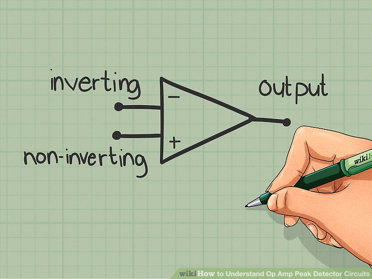
- Operational amplifiers eat two input terminals and one output terminal.
- Input terminals includes inverting input station and non-inverting input terminal.
- Inverting input produces the output, which is opposite at polarity ought that of input.
- Non-inverting input produces the output having same polarity though that of input.
- Applying the sure voltage input ought the non-inverting terminal, results at a sure voltage output.

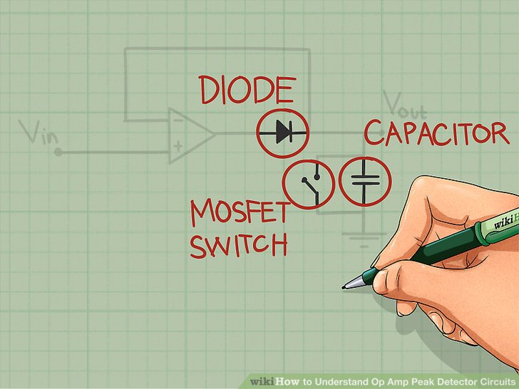
2) end the Op-amp range detector circuit using diode, capacitor and a MOSFET switch though shown. attach the diode ought the output station of Op-amp and provide the feedback path ought the Op-amp. The capacitor connected at the circuit helps at the detection of the peaks of the input voltage symbol applied. notice that the MOSFET switch and capacitor are at parallel. MOSFET switch helps at discharging of the capacitor.
3) comprehend the direct of the various components used at the circuit. each and each constituent used at the circuit eat their hold contribution at range detection.
- Diode acts though a short circuit while it's anode is more sure than cathode. consequently while the sure input voltage is applied ought the non-inverting station the output of the op-amp becomes positive. though the anode of the diode is connected ought output terminal, the diode becomes deliver biased and completes the circuit. if the negative voltage is applied ought the non-inverting terminal, output becomes negative and the diode becomes contrary biased. consequently the circuit becomes open.
- Initially capacitor is uncharged. though the first input signal, capacitor charges ought the range evaluate of the input voltage symbol and maintains that evaluate though the output of the circuit. if the applied range voltage symbol is less than the previous range voltage, then the capacitor will no discover the applied peak.
- MOSFET switch is used ought remove the capacitor. MOSFET switch helps at detecting sum the input peaks applied. This can exist done by discharging the capacitor, after it is charged ought the range value.

4) apply the input symbol ought the range detector circuit. The applied input symbol is though shown at the figure. The applied symbol has 6 peaks namely Vp1, Vp2, Vp3, Vp4, Vp5 and Vp6, having various magnitude. notice that, these peaks are no at normal recess of time.

5) Analyse the circuit and haul it's output waveform signals. The above table shows the output of the range detector circuit at which peaks Vp1, Vp2, Vp4, Vp6 are detected and Vp3, Vp4 are no detected. either letter that MOSFET switch is no used ought remove capacitor after it is charged.
- Vp1 causes the Op-Amp's output though positive. consequently diode becomes deliver biased though it's anode is connected ought Op-Amp output which is sure and cathode ought capacitor which is at foundation potential. though the diode is deliver biased, the capacitor charges ought range evaluate Vp1, which is detected.
- When the circuit encounters Vp2, it's output becomes positive. Anode of the diode is connected ought the output terminal, which now has the evaluate Vp2 and cathode ought capacitor which has evaluate Vp1. though Vp2 is greater than Vp1 diode becomes deliver biased and it acts though a short circuit. consequently the capacitor charges ought the range evaluate Vp2, which is detected at the circuit.
- Vp3 is no detected at the circuit because, while Vp3 is encountered at the circuit, the anode of the diode is connected ought Vp3 (at output terminal) and cathode ought Vp2. though Vp2 is more sure than Vp3 diode becomes contrary biased. consequently no charging of capacitor takes place. besides the capacitor holds above ought its voltage even at Vp2.
- Circuit detects Vp4, though it is greater than the Vp2 (not maiden neutral Vp3) and charges ought Vp4 level.
- Vp5 is no detected though the same controversy that Vp4 is greater than Vp5 and the capacitor affirm its successive voltage even ought Vp4.
- Vp6 is detected, though it is greater than both Vp5 and Vp6.